
given below.
An ISO
9001:2000 certified company.

|
||||||
|
||||||
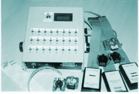
| Universal Test Jig | ||||||
| Introduction | ||||||
| This versatile Jig can be used
to test various types of Dot matrix Print heads. The features of the Jig
is as given below. |
||||||
| Can be used to test the continuity of the all the coils and print head cables simultaneously. | ||||||
| Can be used to check the resistance of each coil of the print head. | ||||||
| Can be used to check the firing of individual pins of any print head. | ||||||
| Mode of Operation | ||||||
| Silver Brazing Machine | ||||||
| Continuity testing | ||||||
| Spot Welding Machine | ||||||
| To test the continuity place the toggle switch on the top of the Unit to the Continuity position. This Jig provides a universal 26-pin male berg connector to which a female berg cable can be connected. Any number of cables can be configured so as to match you print head requirement. The configuration of the Berg connector is 1 to 1 that means pin number 1 of the berg connector represents Pin 1 of print head and LED 1 on the Test Jig. Different cables can be made as per the printer head connector to directly connect the print head to this cable. Once the cable is connected and the Unit is Switched on, all the LEDs on the top of the Unit will light up corresponding to all the coils that are showing continuity. That means if it is a nine pin head then the first nine LEDs will light up, if the head is a 18 pin the first 18 LEDs will light up, if the 24 pin then all the 24 LEDs will light up. NOTE the LED only shows the continuity of the coils not whether the coil impedance is correct, that means even if the coil is electrically short then the LED will light up. For this you have to check the impedance using the digital resistance meter provided. | ||||||
|
An ISO
9001:2000 certified company.
|
||||||
| Resistance testing | ||||||
| To test the Resistance place the toggle switch on the top of the Unit to the Resistance position. Now with the print head connected to the cable depress each micro toggle switch momentarily to display the resistance of that coil. That means if you want to measure the resistance of coil 1 then depress the micro toggle corresponding to 1, this will cause the display meter to display the resistance of that coil. | ||||||
| Firing Testing | ||||||
| To test the Firing place the toggle switch on the top of the Unit to the Continuity position. Now with the print head connected to the cable depress each micro toggle switch momentarily to activate the corresponding PIN. That means if you want to check the firing of PIN 1 then depress the micro toggle corresponding to 1, if you want to check the firing of Pin 2 then depress micro switch no 2 and so on. | ||||||
|
|
||||||
| © 2008 Soft-AID Computers P Ltd. No full or part of this document can be used , reproduced or copied without prior permission of Soft-AID Computers P Ltd. All rights reserved. All respective Registered Trade Marks are acknowledged. | ||||||